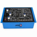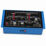
Pulse Width Modulation and Demodulation Manufacturer,Supplier and Exporter in India
Product Code : JA-CT-1498
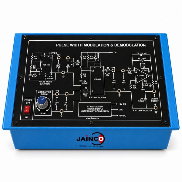
The Pulse Width Modulation and Demodulation board turns a low-level message into a PWM signal and then recovers it. A ramp generator of about 10 kHz and a comparator form the modulator. A second-order low-pass filter near 1.5 kHz and a buffer form the demodulator. Carrier, message, PWM and recovered signals come out at labelled test points.
Specifications of the PWM modulation and demodulation board
| Product code | JA-CT-1498 |
|---|---|
| Power | 12 V DC, from an isolated, regulated 12 V adapter rated at least 0.5 A, with the pin polarity marked; adapter input 100 to 240 V AC, 50/60 Hz* |
| Carrier | Ramp generator of about 10 kHz, with a comparator |
| Message source | Adjustable low-level sine, typically 100 Hz to 1 kHz |
| PWM output | Duty cycle varies within a 10 to 90% teaching window |
| Demodulator | Second-order low-pass filter near 1.5 kHz, with a buffered demodulated output |
| Test points | Carrier, message, PWM and recovered signal at labelled low-voltage test points |
| Size and mass | 300 x 220 x 70 mm (W x D x H), about 1.5 kg |
| Patch cords | 4 mm spring-loaded plugs, stackable from the rear at both ends, 0.5 m |
| Other apparatus required | 20 MHz oscilloscope |
| Manufacturer | JaincoLab, Ambala, India |
* Standard JaincoLab specification for new builds.
PWM experiments with an oscilloscope
- Duty cycle against message level. Show the message and the PWM output together on the 20 MHz Dual Trace Cathode Ray Oscilloscope. Raise the message level and measure how the pulse width follows it within the 10 to 90% window.
- Recovered signal. Compare the recovered output with the message at several message frequencies from 100 Hz to 1 kHz. Note the amplitude and the time delay at each one.
- Filter response. Take the message frequency above 1.5 kHz in steps and plot how fast the recovered output falls. Mark the point where it has dropped to about seven tenths.
- Three pulse methods. Repeat the duty and recovery checks on the Pulse Amplitude Modulation and Demodulation and Pulse Position Modulation and Demodulation boards and compare the three methods.
Frequently Asked Questions
Why is the recovery filter set near 1.5 kHz when the carrier runs at about 10 kHz?
The filter must pass the message, which goes up to about 1 kHz, and block the pulse carrier. A cut-off near 1.5 kHz sits just above the message and well below the 10 kHz carrier. The carrier is then strongly cut while the message comes through with little loss.
Why does the demodulator use a second-order filter rather than a simple RC filter?
A second-order filter cuts frequencies above its cut-off twice as steeply as a single RC stage. With the carrier only a few times higher than the message, a simple RC filter would leave clear ripple on the output. The steeper filter gives a cleaner recovered sine.
How does the message level change the width of the pulses?
The comparator compares the message with the ramp. Its output stays high while the ramp is below the message, so a higher message level keeps it high for longer and widens the pulse. Over one message cycle the width swings between about 10% and 90% of the carrier period.
Which signals should students view together on the dual-trace oscilloscope?
First show the message on one channel and the PWM output on the other, so the width changes line up with the message. Then show the message and the recovered output together to check the shape and the delay. Label each trace in the report with the test point used.
What figures should a tender state for this PWM trainer?
State a 12 V DC board with its isolated 12 V adapter. Add a ramp carrier of about 10 kHz, a 100 Hz to 1 kHz message and the 10 to 90% duty window. Add the second-order recovery filter near 1.5 kHz, labelled test points and a size of 300 x 220 x 70 mm. Send the complete schedule through the tenders page.
Can the PWM board be ordered together with the other pulse modulation trainers?
Yes. The board belongs to the JaincoLab communication trainer range, with pulse amplitude, pulse position, pulse code and delta modulation boards from the same maker. List every board you need in one enquiry through the contact page.
Other pulse modulation trainers
- Pulse Amplitude Modulation and Demodulation
- Pulse Position Modulation and Demodulation
- Pulse Code Modulation and Demodulation Trainer
- Analog Signal Sampling and Reconstruction
See the Communication Trainer range and more electronics lab equipment from JaincoLab, an electronics lab equipment manufacturer in India.
For a quotation, send the product name and the quantity you need through our contact page. For tender or project supply, see our tenders page.