Microwave Training System Manufacturer,Supplier and Exporter in India
Product Code : JA-RATC-9597
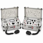
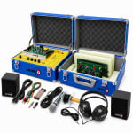
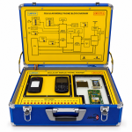
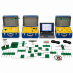
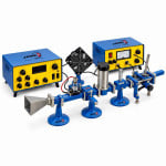
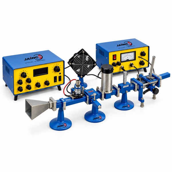
The Microwave Training System is an X-band bench built around one nominal 10.5 GHz source. Its CW or modulated output is 15 mW or less. A matched rectangular waveguide line with attenuator, slotted line, detector, loads and a horn pair lets students measure guided wavelength, attenuation, standing waves and impedance.
Specifications of the microwave training system
| Product code | JA-RATC-9597 |
|---|---|
| Source | One nominal 10.5 GHz X-band bench source, CW or modulated |
| Source power | Low power: 15 mW or less at the source |
| Source supply | Regulated supply with power indication |
| Waveguide line | Matched rectangular waveguide with attenuator, slotted line and detector |
| Terminations | Matched load and further terminations |
| Antennas | Pair of horn antennas |
| Experiments | Guided wavelength, attenuation, standing wave ratio and impedance |
| Use | Stand-alone, or linked with other communications training systems for voice and data transfer |
| Operating note | Operate the bench as the supplied manual describes and under the local radio rules that apply; for bench work, end the line in the matched load so nothing radiates |
| Manufacturer | JaincoLab, Ambala, India |
X-band experiments on the microwave training system
- Guided wavelength. Short the end of the line and move the slotted-line probe to find two neighbouring minima. Twice their spacing is the guided wavelength. Compare the standing-wave idea with the Transmission Line Trainer at lower frequency.
- VSWR and impedance. Fit the matched load, then an unknown termination, and record the maximum and minimum probe readings for each. Work out the VSWR and plot the unknown load on a Smith chart.
- Attenuation. Insert the attenuator between source and detector and note the fall in detector reading at several settings. Compare the results with the attenuator markings.
- Horns and free space. Face the two horns across the bench and study reflection and polarisation. Then repeat the ideas with the Apparatus for Demonstrating Reflection, Refraction, Polarization and Diffraction Using Microwaves.
Frequently Asked Questions
Why does a rectangular waveguide have a cut-off frequency?
A waveguide carries a wave only if the wave fits across its broad wall. Below cut-off, where half a wavelength is longer than the broad dimension, the wave dies away instead of travelling. X-band guides are sized so that a 10.5 GHz source sits well above cut-off in the dominant mode.
How is a high VSWR measured on the slotted line?
For a low VSWR, read the detector at a maximum and a minimum and take the square root of their ratio for a square-law detector. A high VSWR makes the minimum too small to read well, so use the double minimum method. Find the positions either side of the minimum where the reading is twice the minimum, and work from their spacing.
What safety rules apply when students use the microwave bench?
Switch the source off before changing any component, and never look into an open waveguide or a horn mouth while it is on. Keep the end of the line terminated when it is not feeding a horn. Even at 15 mW or less, these habits protect students later on higher-power systems.
Why should the source supply be raised slowly and switched in the right order?
Microwave sources are easily damaged by voltage spikes and reverse polarity. Set the regulated supply to zero, connect the source, then raise the voltage slowly while watching the power indication. Reverse the order when switching off. This protects the oscillator and gives a steady output for measurements.
Which items should a tender list for this microwave bench?
List the 10.5 GHz source and its regulated supply, the matched waveguide line, attenuator, slotted line, detector, matched load and terminations, and the horn pair. State the experiments needed, such as guided wavelength, VSWR and impedance. Ask for the source frequency tolerance and power to be stated from the data of the oscillator supplied.
Can your engineers install and test the bench at our laboratory?
Yes. JaincoLab service engineers install the bench at your site and check it with your staff, and a team can demonstrate the experiments. The horns radiate a low-power 10.5 GHz signal, so users follow the supplied manual and the local radio rules that apply.
Other trainers in the radio and telephone range
- CB Transceiver Trainer
- AM FM Radio Trainer
- Radio Communication Training System
- Integrated AM and FM Trainer
- Walkie Talkie Trainer
- Antenna System Demonstrator
See the Radio and Telephone Communications range and more electronics lab equipment from JaincoLab, an electronics lab equipment manufacturer in India.
For a quotation, send the product name and the quantity you need through our contact page. For tender or project supply, see our tenders page.